Computer Networking Chapter 2 (Layer 3-4)
Categories: Computer Networking
Tags: Computer Networking
Important Words to Remember:
Node: It is the connection point in a network. Examples include hubs, switches, computers etc.
Interface: It is the port on the node in a network. They can either be physical (like NICs which make up an ethernet port), or virtual (like loopback or VPN).
PDU (Protocol data unit): The small data units used to slice chunks into smaller/more specialized chunks. Segments, packets, datagrams, and frames are all PDU.
Fragmentation: The process exclusively in OSI layer 3 that involves slicing packets into smaller pieces.
Segmentation: The process exclusively in the OSI layer 4 for the TCP protocol that involves the slicing of data stream into smaller pieces.
Encapsulation: Adding a new header/info to a PDU.
Decapsulation: Removing a header/info to a PDU.
Packets: The PDU of the Internet layer in the TCP/IP model.
Segments: PDU for OSI layer 4 (transport layer) for TCP related tasks.
Datagram: PDU for OSI layer 4 (transport layer) for UDP related tasks.
TCP (Transmission Control Protocol):
- An OSI layer 4 protocol for loading a webpage, exchanging messages, email, and anything else that involves reliability instead of speed.
- It uses segmentation before being transmitted.
- Unicast uses TCP only.
UDP (User Datagram Protocol):
- An OSI layer 4 protocol for game servers, VoIP (Viber, WhatsApp, Telegram etc.) and other time-sensitive applications.
- It does NOT use segmentation before being transmitted.
- Multicast and broadcast usually use UDP.
IP: An OSI layer 3 protocol that defines how to address and route packets for delivery.
Understanding TCP/IP Protocol Suite
Recalling from the previous chapter, TCP/IP suite is a collection of protocols that allows connectivity between different local or remote networks. It covers layer 3 to layer 7 of the OSI model.
Here is a table to illustrate:
| TCP/IP Layer | OSI Equivalent Layer(s) | Common Protocols | PDUs (Protocol Data Units) at this layer |
|---|---|---|---|
| Application | Application, Presentation, Session | HTTP, HTTPS, FTP, SMTP, POP3, IMAP, DNS, SSH, Telnet, SNMP | Data, Messages, Streams |
| Transport | Transport | TCP, UDP | Segments (TCP), Datagrams (UDP) |
| Internet | Network | IP (IPv4, IPv6), ICMP, ARP, IGMP | Packets (or Datagrams) |
| Network Access | Data Link, Physical | Ethernet, Wi-Fi (802.11), PPP, Frame Relay, ATM | Frames (at Data Link), Bits (at Physical) |
They function together and are collevtively named due to both TCP and IP being ubiquitous protocols.
Note: The reason why it is not "UDP/IP" is because TCP is older than UDP. Moreover, most TCP/IP suite applications require TCP to function because it is much more dominant than UDP.
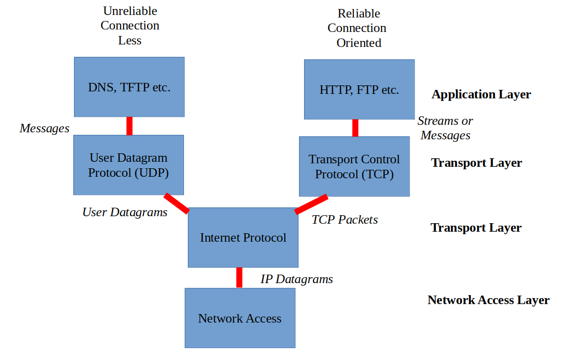
Ok, but what do protocols have in common?
They are categorized into numerous separate categories. Here are four well-known ones:
- Connection-Oriented Protocols: Involve two hosts making assurances (ex: "handshake process") and establish an agreement prior to any data being exchanged.
- Ex: TCP, SCTP, ATM
Note: Protocols are often reliant on other protocols to function. Some of the most common protocols that we use like SMTP or IMAP for mails, FTP for file transfers, and SSH for remote computer access need TCP in order to function. This is why unlike the SCTP and ATM, TCP stands out because it has better support and is the most common.
-
Connectionless Protocols: Involve a host releasing data to another without any prior acknowledgement or any pre-arranged preparations. It spews out data without any verifications.
- Ex: UDP, IP, ARP
-
Stateful protocols: Keep track of each packet during a session in order to quickly retransmit data in case of a network failure.
- Ex: FTP, TCP, SSH
-
Stateless protocols: Do not remember or track packets during a session. Data is picked up where they were left off once a connection gets reestablished.
- Ex: IP, HTTP, DNS
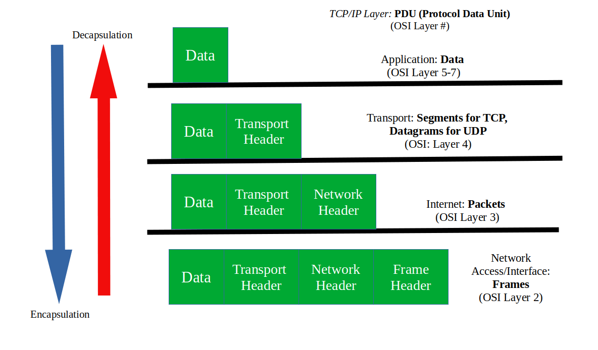
Understanding PDUs
It is important to note that TCP/IP deals with packets and segments/datagrams, not frames.
Here is an image to illustrate what a packet looks like. It is essentially data wrapped around lower-level data just like an egg:

Here are the PDUs that you need to learn:
- Frame: PDU of OSI Layer 2
- Packet:
- Generic meaning: Any data that are grouped together as a bundle.
- Specific meaning: PDU OSI of Layer 3
- Segment: TCP PDU of OSI Layer 4
- Datagram: UDP PDU of OSI Layer 4
In a colloquial setting, all of the PDUs mentioned above can be referred to as "packets" unless otherwise noted.
Ok, but what about OSI layer 1?
OSI Layer 1's PDU is just "bits" or "symbol sequences". They are just raw streams of 1s and 0s. They bear no logical structure and only bring signals (electrical/light impulses or radio waves) across the physical medium.
TCP/IP in Action
When PDUs traverse across the network, information gets added as they leave the client to a remote destination. They go through several layers in the OSI model before they are disassembled when they arrive at their destination.
Encapsulation to Decapsulation:
In order to understand how either encapsulation or decapsulation work, it is better to provide a real life example of a packet being assembled and sent over from one host to the other.
Let's say PC1 wants to send a file to PC2 via an Ethernet cable or wirelessly using an SSH session with the scp command. The concise steps to achieve this are as follows, starting with TCP/IP's Application Layer:
- Application Layer:
- As the SSH session begins, PC1 must resolve PC2's hostname to an IP address. Only one of the following scenarios happen:
- If PC2's IP address is not found, PC1's Domain Name System (DNS) resolver will ask the DNS server (often the home router) to obtain it.
- If found, it is done by checking though PC1's hosts file or DNS cache in memory.
- When the client generates the data necessary to peform a particular action, it will be formatted and ecrypted through SFTP.
- Once data is ready, it gets passed down to the Transport layer.
- Transport Layer:
-
Because the Application Layer's SSH request requires a connection-oriented protocol, TCP will be used.
-
Since TCP requires proper ordering to prevent packet loss or misordering, it divides data into little chunks of manageable PDUs ("segmentation") called "segments".
-
After segmentation, new information gets added or encapsulated into segments. This forms the segment header that contains the source and destination port numbers. This is done in order to identify the application process on both hosts (the destination port number will be 22)
Note: There are two things to be aware of:
- Usually when a header is added, it is not just source/destination fields. There are many more fields that are added to the header that they are beyond the scope of this chapter. For now, it is important to know the most notable fields are the source/destination ones.
- The most common confused Transport Layer aspect is how the source port and the destination port are not equal to each other: We go through port numbers here.
-
Once the data is segmented and the Transport Layer header is fully assembled, the segment will be passed down to the Internet Layer.
- Internet Layer:
- Once the Transport Layer segment is received, Internet Protocol (IP) will be used to prepare routing.
- TCP segment is now encapsulated within the IP header to form a new PDU called "packet". If the size of the packet exceeds the Maximum Transmission Unit (MTU), it will go through a process called "fragmentation" in order to achieve proper processing of data by the destination (PC2).
- The packet now holds both the source and the destination's IP addresses that are initially retrieved and carried over from the Application Layer. It finally has the information needed for the location to be sent based on the destination address alone.
- Network Access Layer:
- As the IP packet arrives at this layer, one final encapsulation is required before a transmission takes place.
- The IP packet is now encapsulated into an Ethernet frame by adding an Ethernet header (which includes MAC addresses) and a trailer (used for error detection).
- The frame now heads off to the physical layer for delivery across the network.
As the frame arrives at its destination, one of the two scenarios happen:
- If unsuccessful: The Time to Live (TTL) field in the IP header decrements by one count with every router hop. For this case, the IP packet is not discarded nor the TTL is decremented because both hosts belong in the same network and are at a short distance between each other.
- If successful: The IP packet is in tact and the PC2 will reverse the adding of data through the processes of decapsulation. The headers are removed until data gets processed by the Application Layer.
- The copied file is now accessible in the current working directory.
OSI Layer 3 and 4
Layer 3 (network layer) is the layer where routing takes place. It is where former frames (now called packets), move from one network to another. It forms the basis of the internet.
OSI Layer 3
IP (Internet protocol) is the most important protocol out of all the OSI model. Without IP routing, there will be no internet:
- It implements the logical aspect of networking:
- It relies on IP addresses to enable internetwork routing.
- It is a connectionless protocol:
- IP relies on other protocols for verification and to establish a secure connection.
- IP is responsible to help route packets between different networks:
- It implements the routing aspect of the network but it does not oversee them. It is only for identification purposes.
IP comes with IP addresses. They sit on top of networking interfaces on any computer. They are either routers, switches, PCs, etc. They all connect together to perform the tasks needed to form a network.
The most popular devices that belong in layer 3 are routers and switches (not to be confused with layer 2 switches).
IP addresses sit on top of router or switch interfaces (i.e. gigabitEthernet0/0/0, fastEthernet0/0/0, etc.) to make IP reliable.
Explaining IP Addresses
Recall that layer 2 relies on MAC address. Layer 3 however, relies on IP addresses.
IP (internet protocol) address: It identifies a device on a local network and operates at level 3 of the OSI model. Unlike MAC addresses that are permanently embedded in NICs, they are configured in any layer 3-supported device's operating system (i.e. PCs, switches, routers).
All IP addresses consist of two parts:
- Host ID: Identifies the host portion of the IP address.
- Network ID: Identifies the network portion of the IP address.
There are two popular types of IP addresses, IPv4 (32-bits) and IPv6 (128-bits). They can all be either public, private, static, or dynamic.
-
Static IP address: IP addresses that do not change over time.
-
Dynamic IP address: IP addresses that can change over time.
-
Public/external IP address: IP addresses that are acccessible outside the local network. It is no different to a home addresses.
-
Private IP address: IP addresses that are only accessible to hosts connected on the same network.
Recall:
A "bit" is one digit that is either one or zero. Therefore, an octet is 8 "bits" of ones and zeroes.
In computer science, the word "byte" is used more commonly instead of "octet". Because "byte" did not historically always mean 8 bits, the word "octet" better fits the description.
Note:
- In computer networking terminology:
- "octet" == "8 bits"
- "hextet" == "16 bits"
Let's discuss the history then dive deeper into IPv4 and IPv6 respectively:
History of IP
- The Experimentation Age (1980-1981): Initially, it was decided to only have the first 8-bits (octet) of an IPv4 address to define the network of a given host. This made the internet to only have 254 usable networks (2 addresses were reserved from 256). As you may well know, the internet has far more than 254 networks today.
- Here is RFC 762 to see the various highest networking numbers with internet access back in 1980.
- Networking numbers: Back in the days before regional internet registries, IPv4 address blocks were called "network numbers". They had to be manually allocated across educational institutions, government bodies, scientific labs etc. They were all overseen by the famous Jon Postel.
-
The Classful Age (1981-1993): It was later decided to divide IPv4 addresses into fixed-size classes to accommodate different network sizes. By the time IPv4 became widely available in 1983, it was still not a sufficient way to resolve IPv4's rapid growth in the long-term.
- Although the following table is a bit outdated for practical use, it is often shown in textbooks as to provide better context of IPv4:
Note:
- 255.255.255.255 is exlucded in this table as it is exclusively used for broadcasting the entire local network.
- IPv4 addresses that start with 127 is exlucded because they are now reserved for loopback addresses.
First Decimal Value Addresses Hosts per Network ID Class A 1-126 1.0.0.0 - 126.255.255.255 16,777,214 Class B 128-191 128.0.0.0 - 191.255.255.255 65,534 Class C 192-223 192.0.0.0 - 223.255.255.255 254 Class D 224-239 224.0.0.0 - 239.255.255.255 Multicast Class E 240-255 240.0.0.0 - 254.255.255.255 Reserved
- The Classless Age (1993-present): Classless addressing (Class Inter-Domain Routing or CIDR) was introduced to resolve IPv4 waste. This was to enable companies divide networks to their own liking instead of being limited to five IPv4 classes. For example, if a company has 67,000 hosts, it will waste over a thousand addresses. This is unimaginable for today's standards.
Overall, IP has had 4 upgrades since the 80s:
- Private addressing: It is a remnant of IPv4 classes that allow IPv4 address chunks to be reusable for private networking use.
- CIDR/classless addressing: Allows network admins to lessen IPv4 exhaustion by dividing networks into smaller, scalable networks (aka "subnetting").
- NAT: Allows multiple private networks to be represented as one Public IP address.
- Loopback address: It is the internal mock networking address of the system and is used to troubleshoot TCP/IP. It is also known as "localhost".
- IPv6: A successor of IPv4 that is in use since 2012. Both IPv4 and IPv6 are widely used.
- I recommend watching Vint Cerf's interview on this. Here, he discusses on what lead to IPv6.
IPv4
IPv4 uses a dotted decimal notation which consists of four sets of numbers that are separated by a period (.). Each set is 8 bits (one octet) that ranges from 0 to 255 inclusive. In total, it uses 32-bits (or 4 octets).
This is what an IPv4 address looks like:
192.168.18.146
Ok, but how did this all come to be?
Since all computation and data allocation are done in binary, a fixed number of bits were required to designate an IP address. For DARPA back in the 1970s, it was originally decided that 32 bits would be sufficient.
To "feel" the sense IP addresses, I highly recommend watching this video by Carl Oliver. It perfectly captures the context of binary and decimal conversion for IP addresses:
Here is the conversion done in reverse (binary to decimal):
As computers only understand binary, this is what they would see (based on the last example):
11000000101010000001001010010010
In order to make this more legible, we add in a dotted decimal notation:
*1 octet* *1 octet* *1 octet* *1 octet*
  |          |         |         |
  V          V         V         V
11000000.10101000.00010010.10010010
To convert it back to decimal, each octet must be within the range 0-255 inclusive. Therefore, we need to perform a conversion one by one.
Let's take the first octet 11000000...
| Binary Digit | 1 | 1 | 0 | 0 | 0 | 0 | 0 | 0 |
|---|---|---|---|---|---|---|---|---|
| Power of 2 | $2^7$ | $2^6$ | $2^5$ | $2^4$ | $2^3$ | $2^2$ | $2^1$ | $2^0$ |
| Decimal Value | 128 | 64 | 0 | 0 | 0 | 0 | 0 | 0 |
| Total: 192 |
We repeat this for every octet to get back to this:
192.168.18.146
You've mentioned that all IP addresses have two parts, the Network ID and the Host ID. How do we determine them for IPv4 addresses?
We use a subnet mask to determine the Host ID and the Network ID. It will be impossible for an IPv4 address to be reachable without it.
If we take the same address from last time:
192.168.18.146
And have our subnet mask be assigned like this:
255.255.255.0
We can tell the Network ID and the Host ID by the two portions of 255s and 0(s) respectively. In this case:
- Network ID: 192.168.18.0
- Host ID: 0.0.0.146
Let's take another IPv4 address:
10.5.20.75
And if our subnet mask is:
255.255.0.0
Then our Network ID and our Host ID are as follows:
- Network ID: 10.5.0.0
- Host ID: 0.0.20.75
How can a subnet mask be concisely represented alongside an IPv4 address?
We use the CIDR notation for this precise use.
Let's bring back our first IPv4 address and its subnet mask as an example:
  192.168.18.146
  255.255.255.0
The shorthand for this is:
192.168.18.146/24
The number '24' represents the Network ID with the number of bits assigned to 1. Here is a representation of the subnet mask in binary and its decimal form:
  11111111.11111111.11111111.00000000
  255.255.255.0
The '1's pertain to the Network ID while the '0's pertain to the Host ID. By counting the number of '1's in the Network ID portion, we get 24.
What were the cons of IPv4?
It lead to the exhaustion of IPv4. The consequences if ignored were tremendous:
- There was a need for better IPv4 allocation for large corporations and government institutions.
- Increase demand of networking infrastructure as it was becoming cheaper to build.
- Routers could not handle large routing tables, leading to performance issues.
Private addressing is defined in RFC 1918. This became a standard for routers to never use one of the three IP ranges below for public routing:
| Private IP Range | CIDR Notation | Number of Addresses | Common Use Cases |
|---|---|---|---|
| 10.0.0.0 – 10.255.255.255 | 10.0.0.0/8 | 16,777,216 | Large internal enterprise LANs |
| 172.16.0.0 – 172.31.255.255 | 172.16.0.0/12 | 1,048,576 | Medium-scale networks |
| 192.168.0.0 – 192.168.255.255 | 192.168.0.0/16 | 65,536 | Home and small office LANs |
Within each row in the table above, we see a block of private IP addresses and CIDR notations used as a shorthand to represent the network id and the host ID.
Note:
- Just because there is a private network starting with 10.x.x.x, it doesn't always mean the CIDR notation is always /8. It can be /24 through subnetting (dividing a local network into smaller sections). Only a portion of the "172" and "192" address ranges are designated for private use (hence /12 and /16 respectively).
All these implementations were not enough to permanently resolve IPv4's problems. Over time, an entirely new IP address was needed to ensure proper routing alongside IPv4.
IPv6
IPv6 is the most recent version of IP and is an improved version of IPv4. Unlike IPv4 using 32-bits, it uses 128-bits.
IPv6 addresses are separated by a colon (:) into eight sections of 16 bits (one hextet). Each segment uses a hexadecimal notation ranging from 0 to ffff.
This is what an IPv6 looks like:
2001:db8:3333:4444:5555:6666:7777:8888
In a home environment, it is the responsbility of the Internet Service Provider (ISP) to configure dynamic IP addresses automatically through a protocol called DHCP (Dynamic Host Control Protocol). They also provide other parameters like subnet masks and default gateways automatically.
For more information about IPv4, IPv6 and IP addressing, there will be a dedicated article in the works.
OSI Layer 4
OSI layer 4 helps coordinate packets to their destination. It is the "how" for layer 3.
Clarifying the "how"
The most common protocols for Layer 4 are TCP and UDP. Each protocol has different applications but serve the same purpose as they are run on top of IP.
So if Layer 2 has MAC addresses, Layer 3 has IP addresses, what does Layer 4 have?
Port numbers
As the packet gets delivered to a destination with a particular IP address, the sending application will still need to provide clarification on what port number will be used. This is because the receiving end's operating system (application layer) needs to know which specific service the data is intended for.
Here is a table of some of the most well-known port numbers, all corresponding to an application layer protocol that utilizes both TCP and UDP:
| Port Number | Service/Application | Protocol |
|---|---|---|
| 20 | FTP (Data) | TCP |
| 21 | FTP (Control) | TCP |
| 22 | SSH (Secure Shell) | TCP |
| 23 | Telnet | TCP |
| 25 | SMTP (Simple Mail Transfer Protocol) | TCP |
| 53 | DNS (Domain Name System) | Both TCP and UDP |
| 67 | DHCP (Server) | UDP |
| 68 | DHCP (Client) | UDP |
| 80 | HTTP (Hypertext Transfer Protocol) | TCP |
| 110 | POP3 (Post Office Protocol version 3) | TCP |
| 123 | NTP (Network Time Protocol) | UDP |
| 143 | IMAP (Internet Message Access Protocol) | TCP |
| 161 | SNMP (Simple Network Networking Protocol) | UDP |
| 443 | HTTPS (Hypertext Transfer Protocol Secure) | TCP |
If both hosts are getting the data they need to process, wouldn't they use the same port number?
No. Let's take an example:
If I have a computer with one browser tab open that uses port 443 while connecting to a website that uses the same port number, a second tab making the same request cannot use the same port number again. Each inbound port must be unique.
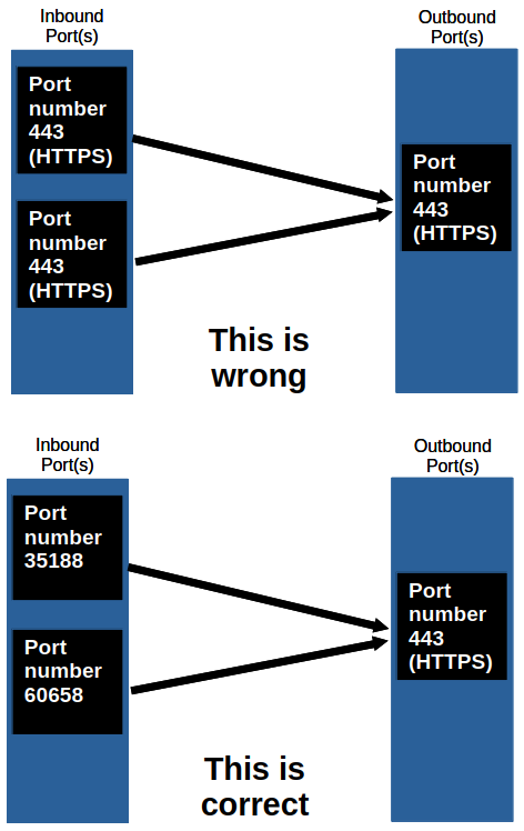
This is done by setting the source port to a random temporary number. It is called "ephemeral ports" (also known as private or dynamic ports).
To see this in practice, type in ss -tun to see both inbound and outbound UDP and TCP ports on Linux or netstat -an -p tcp on Windows.
Ephemeral Port: They are temporary ports in OSI layer 4 used by client applications when initiating a connection to a server. Unlike reserved ports from the table above, they are allocated from a specific range defined by the operating system for the duration of the communication session.
Here is a table to show the ranges for an ephemeral port specified by the operating system:
| Category | Recommended Range (IANA) | Common Linux Default Range | Common Windows Default Range (Vista and later) | Common macOS Default Range |
|---|---|---|---|---|
| Ephemeral Ports | 49152-65535 | 32768-60999 (can vary) | 49152-65535 | 49152-65535 |
When I develop a web app, I see the word "sockets" show up quite often. Are they related to port numbers?
Yes. In fact, socket = IP address + port number.
If you use Linux, you can type ss -tun to see both TCP ports and the UDP ports (-n shows the exact port number instead of the name of the protocol). What you may find is show the port number comes right after the IP address.
TCP
Transmission Control Protocol (TCP) is a connection-based protocol that defines a set of rules to establish or terminate connectivity between two different hosts.
Recall from the previous chapter about PDUs...
So what we'll get is this:
IP packet = IP header + IP payload
IP payload = TCP header + TCP payload
TCP payload = Data
To better observe the TCP segment, this is how RFC 793 illustrates it. For now, it's important to focus on the fields Source Port, Destination Port, Sequence Number, Acknowledgement Number, Control Bit fields, and Data:
 +-+-+-+-+-+-+-+-+-+-+-+-+-+-+-+-+-+-+-+-+-+-+-+-+-+-+-+-+-+-+-+-+
 |          Source Port          |       Destination Port        |
 +-+-+-+-+-+-+-+-+-+-+-+-+-+-+-+-+-+-+-+-+-+-+-+-+-+-+-+-+-+-+-+-+
 |                        Sequence Number                        |
 +-+-+-+-+-+-+-+-+-+-+-+-+-+-+-+-+-+-+-+-+-+-+-+-+-+-+-+-+-+-+-+-+
 |                    Acknowledgment Number                      |
 +-+-+-+-+-+-+-+-+-+-+-+-+-+-+-+-+-+-+-+-+-+-+-+-+-+-+-+-+-+-+-+-+
 |  Data |           |U|A|P|R|S|F|                               |
 | Offset| Reserved  |R|C|S|S|Y|I|            Window             |
 |       |           |G|K|H|T|N|N|                               |
 +-+-+-+-+-+-+-+-+-+-+-+-+-+-+-+-+-+-+-+-+-+-+-+-+-+-+-+-+-+-+-+-+
 |           Checksum            |         Urgent Pointer        |
 +-+-+-+-+-+-+-+-+-+-+-+-+-+-+-+-+-+-+-+-+-+-+-+-+-+-+-+-+-+-+-+-+
 |                    Options                    |    Padding    |
 +-+-+-+-+-+-+-+-+-+-+-+-+-+-+-+-+-+-+-+-+-+-+-+-+-+-+-+-+-+-+-+-+
 |                             data                              |
 +-+-+-+-+-+-+-+-+-+-+-+-+-+-+-+-+-+-+-+-+-+-+-+-+-+-+-+-+-+-+-+-+
But hang on a moment, we need to know TCP's three stages:
-
Session Establishment: Enables host-to-host communication as two computers establish a reliable connection through a process called "three-way handshaking". It has to start before data transfer and it will require both hosts to exchange on a maximum segment size (MSS) of their own choosing. and a window Size.
-
Data Transfer: Both hosts send and receive packets of data bidirectionally. This will continue as long as the session is active.
-
Session Termination: When a TCP session ends, a "four-way handshake" will start when both hosts agree to terminate the session. This can be done when the server finishes sending the data to the client.
Ok, so all of this is facilitated with a field from the header known as "control bits". They are explicitly defined in TCP headers to control establishing connections, connection abortion, flow control, mode of transfer etc.
There are six control bits:
-
URG (Urgent Pointer field significant): When this bit is set to 1, the data has more priority over other data.
-
ACK (Acknowledgment field significant): Acknowledgement of received data from a client/server.
-
PSH (Push Function): Tells the transport layer that the data should be sent immediately even if the maximum segment size (MSS) is below a specified number of bytes. In other words, a segment with this bit set to one will be immediately forward itself to the next layer because the payload size is below the max MSS.
-
RST (Reset the connection): This is enabled if there is a need to immediately end TCP transmission. The flag will be known to the client when the browser tab is closed before a webpage loads.
-
SYN (Synchronize sequence numbers): This bit is set to one only twice in the three-way handshake session. It initializes the initial sequence number (INS) to a random number that will be assigned to a sequence number (SEQ) field. The SEQ number is a field in the TCP header used to keep track of how much data is sent since the three-way handshake.
-
FIN (No more data from sender): Unlike RST, it cleanly terminates a session.
Here is an example of how a TCP conversation starter (three-way handshake) would look like from a Layman's perspective. Let's say PC1 is someone's PC while PC2 is a web server:
  Alice: "Are you there?" (Synchronizing... [SYN])
  Bob: "Yes, I am here. Are you ready?" (Acknowledging and Synchronizing... [SYN-ACK])
  Alice: "Ok, I am here and ready." (Acknowledging... [ACK])
So:
- Alice initiates the connection by sending a packet with the SYN bit set to 1.
- Bob responds with a packet that has both the SYN bit and the ACK bit set to 1.
- Alice completes the handshake by sending the final packet with its ACK bit set to 1.
From here on, the only ACK control bits will be used to keep track of the session.
Now, this is an example of how a TCP three-way handshake actually (RFC793 Section 3.4) looks like:
      Alice                                                Bob

  1.  CLOSED                                               LISTEN

  2.  SYN-SENT    --> <SEQ=100><CTL=SYN>               --> SYN-RECEIVED

  3.  ESTABLISHED <-- <SEQ=300><ACK=101><CTL=SYN,ACK>  <-- SYN-RECEIVED

  4.  ESTABLISHED --> <SEQ=101><ACK=301><CTL=ACK>       --> ESTABLISHED

  5.  ESTABLISHED --> <SEQ=101><ACK=301><CTL=ACK><DATA> --> ESTABLISHED
Line 1: Both Alice and Bob are yet to send anything to each other.
Line 2: Alice picks up a random number 100 then sends a segment with the SYN flag set to one. Alice is confirming the SYNchronization of her INS 100. This INS will immediately be Alice's base number for her succeeding SEQ numbers.
Line 3: Bob picks up Alice's packet. He starts the SYNchronization of its own INS number then simultaneously ACKnowledges Alice's INS number plus one (100+1=101. This is how Bob "became aware" of Alice's INS). In the meantime, Bob is expecting 101 from Alice's SEQ field in her succeeding packet.
Line 4: Alice sends her ACKnowledgement of Bob's INS plus one (300+1=301). Alice is now ready to send data to Bob.
Line 5: Alice sends the same packet but with data this time.
For tldr readers out there, this is the three-way handshake summary:
- A --> B: SYNchronize with my INS of X.
- A <-- A: I received your SYN, I ACKnowledge that I'm ready for [X+1].
- A <-- B: SYNchronize with my INS of Y.
- A --> B: I received your SYN. I ACKnowledge that I'm ready for [Y+1].
Okay, after line 5, we finally get to see Alice and Bob forwarding packets like normal. Here is a high-level description of the process:
Alice: I want to send you some data. It will be in 12 packets, each 256 bytes long.

Bob: I am ready to receive packet 1 of 12.

Alice: I am sending packet 1 of 12, it is 256 bytes long.

Bob: I have received packet 1 of 12, it was 256 bytes long. I am ready to receive packet 2 of 12.

Alice: I am sending packet 2 of 12, it is 256 bytes long.

Bob: I have received packet 2 of 12, but it was only 183 bytes long. Please resend.

Alice: I am sending packet 2 of 12, it is 256 bytes long.

Bob: I have received packet 2 of 12, it was 256 bytes long. I am ready to receive packet 3 of 12.
Now here is a low-level description:
    Alice                                                           Bob

  1.  ESTABLISHED -->   <SEQ=101><ACK=301><CTL=ACK><DATA=256>   --> ESTABLISHED
      (Alice sends Packet 1)

  2.  ESTABLISHED <--   <SEQ=301><ACK=357><CTL=ACK>             <-- ESTABLISHED
      (Bob says: "Got it! Send me byte 357 next.")

  3.  ESTABLISHED -->   <SEQ=357><ACK=301><CTL=ACK><DATA=183>   --> ESTABLISHED
      (Alice sends Packet 2, but it's truncated/corrupted to 183 bytes)

  4.  ESTABLISHED <--   <SEQ=301><ACK=357><CTL=ACK>             <-- ESTABLISHED
      (Bob says: "Wait, I'm still expecting 357. I won't ACK the 183 bytes.")

  5.  ESTABLISHED -->   <SEQ=357><ACK=301><CTL=ACK><DATA=256>   --> ESTABLISHED
      (Alice realizes the ACK didn't advance and resends Packet 2)

  6.  ESTABLISHED <--   <SEQ=301><ACK=613><CTL=ACK>             <-- ESTABLISHED (Bob says: "Perfect. 357 + 256 = 613. Send me 613 next.")
As computers send data to each other, each TCP/IP layer will either strip (segmentation) or join chunks of data together (encapsulation) as they move towards or away from the application layer.
So if one host were to transmit data, TCP will slice the data into segments and wrap each segment with a header (containing all the necessary information) before sending it to the other end.
I highly recommend watching this video from Practical Networking explaining TCP for an excellent video reference:
I also recommend giving this article and this one a read as well.
UDP
UDP is a connectionless-based protocol that doesn't negotiate or keep track of records. Compared to TCP, it is extremely bare-bones and less "intelligent".
- Unlike TCP, the application layer has to strip data on its own before being transmitted.
- Packets will be sent and can be dropped in a different order than they were transmitted.
- They are sent to the receiver directly without authentication (no three-way handshaking and no four-way handshaking).
- Unlike TCP, UDP does not have any recovery of lost or corrupted data. It only has a mechanism to detect lost or out of order packets. That's why UDP is sometimes referred to as "Unreliable Data Protocol"
- UDP is excellent for time sensitive applications of multiplayer video games, streaming movies or music, and VoIP video call.
Reading through RFC 768, we'll find this:
+--------+--------+--------+--------+
|     Source      |   Destination   |
|      Port       |      Port       |
+--------+--------+--------+--------+
|                 |                 |
|     Length      |    Checksum     |
+--------+--------+--------+--------+
|
|          data octets ...
+---------------- ...
     User Datagram Header Format
Length is the number of octets of data including the header.
Checksum is a 16-bit field and is there only to detect computer corruption.
This is how the checksum is involved:
- The sender computes the checksum based on the data in the segment.
- The sender stores the checksum in the field.
- When the datagram arrives, the receiver computes the checksum from the received data on its own.
- If the receiver's and the sender's checksum do not match, the receiver will discard the datagram entirely. This explains why multiplayer can be slow at times or how video calls can momentarily stop then come back again.