Computer Networking Chapter 1 (Layer 1 and 2)
Categories: Computer Networking
Tags: Computer Networking
Important Words to Know
Node: It is the connection point in a network. Examples include hubs, switches, computers etc.
Port: It is a communication endpoint of a computer hardware/program. They are either physical or logical (non-physical).
Server: A computer program/hardware that provides data to another computer program/hardware.
Client: A computer program/device that receives data from a server.
Protocol: A set of instructions to enable data transmissions between different devices within a network.
OSI (Open Systems Interconnection) Model: A reference model that provides a standard for nodes to communicate using standard protocols. It is made up of seven layers and is often used for accurate troubleshooting.
TCP/IP (aka Internet Protocol Suite): An older reference model that predates the OSI model. It is used for often used for more practical purposes. Unlike the OSI model, it has four layers.
Broadcasting: The process of sending data to all devices on a local network.
MAC Address: A unique OSI Layer 2 identifier for network devices like computers, switches, routers or any other layer 2 compatible devices.
NIC (Network Interface Card/Controller): It is a hardware component that acts as an interface between the computer and the network and facilities their communication.
Frame: It is a data unit within the data-link layer of the OSI model (layer 2).
Unicast frame: A frame dedicated to a specific device on the local network.
Unicast addressing: The ability of which the unicast frame was sent to a specific device.
Payload: The position in the PDU containing the actual data made up of bits sent by the client (Ex: text or image).
Header: The initial position that precedes the payload in a PDU. It provides the metadata necessary for proper directions and processing. (Ex: Ethernet header, IP header, TCP header, UDP header etc.).
Trailer: The final position of a frame containing metadata to check its validity (error detection) or signal the end of a frame.
Introduction
The OSI Model
How does networking work? Is it magic?
To answer this question, one has to make a diagram or a model of some kind to better illustrate computer networking. There are too many protocols that can overlap and have similar-sounding acronyms. As a result, they have to be grouped into separate, independent layers.
OSI (Open Systems Interconnect) model:
| Layer # | Description |
|---|---|
| Layer 7 | Application |
| Layer 6 | Presentation |
| Layer 5 | Session |
| Layer 4 | Transport |
| Layer 3 | Network |
| Layer 2 | Data Link |
| Layer 1 | Physical |
The OSI model was developed by ISO (International Organization for Standardization) that helped standardize computer networking. It helped each layer to express its own functionality with little to no interaction with other layers. It is simple and is modular by design.
Note:
- OSI Layer 2 is often divded into two sub-levels: Logical Link Control (LLC) and Media Access Control (MAC).
- OSI Layer 2 is the only OSI layer with sub-layers.
We will go over Layers 1 and 2 in this chapter.
The TCP/IP Model
Another model to consider is the TCP/IP model. It is a simpler version of the OSI model.
| TCP/IP Layer # | TCP/IP Layer | OSI Model Layer |
|---|---|---|
| 1 | Application | Application |
| Presentation | ||
| Session | ||
| 2 | Transport | Transport |
| 3 | Internet | Network |
| 4 | Network Interface | Data Link |
| Physical |
TCP/IP model came out 10 years before the OSI model. It is inspired by the ARPANET Reference Model operated by the US Department of Defense.
These two models are extremely important when you want to be acquainted into computer networking. It is advised to memorize their layers as they will be asked during exams.
My favourite way to remember the OSI model is "Please Do Not Teach Students Pointless Acronyms" (credit to u/ArchaonX). Feel free to create or use other interesting ones :)
Layer 1 and Layer 2 Explained
OSI Layer 1
For a device to be considered layer 1:
- It must only pocess the capability to transmit a stream of raw bits over any medium.
- It only covers the physical aspect without any interpretation of data.
- It relies on electricity, light, or electromagnetic waves.
Such applications of layer 1 devices include cables, hubs, and repeaters. There are some devices that overlap with different layers (NICs and modems) but still perform core physical functions.
In this chapter, we will focus on cables and hubs.
Cables
We all know what cables are don't we? They're just a bunch wiiiiiires... right?
To clear any confusion:
- Wire: It is a thin shred of an electric conductor (usually copper or aluminum).
- Cable: It is a bundle of electrical wires ecased in sheathing.
Cables only transmit data and do not posses intelligent solutions. They rely on conductors that create current in order to move data from one system to another. Furthermore, bandwidth
Note: Not all wires use metal. There are optical cables that use light or lasers to transmit data and are covered with insulators like pure glass or plastic.
Every cable comes with a terminus called a connector. It acts as an interface to allow attaching a networking device physically and electrically. The most well-known connector is RJ-45 and is used for ethernet connectivity.
Cables mostly come into three different forms: Twisted, Coaxial, and Fiber. Here is a table to illustrate:
| Type | Sub-Type | Examples/Uses | Common Connectors |
|---|---|---|---|
| Twisted Pair | Shielded Twisted Pair (STP) | Cat5, Cat5e, Cat6, Cat6a, Cat7 | RJ-45 |
| Unshielded Twisted Pair (UTP) | Cat3, Cat5, Cat5e, Cat6, Cat6a, Cat8 | RJ-45 | |
| Coaxial Cable | RG-6 | Commonly used for cable TV and internet | F-Type, BNC |
| RG-11 | Longer-distance applications | F-Type, BNC | |
| RG-58 | Used in legacy Ethernet networks | BNC, N-Type | |
| Fiber Optic Cable | Single-Mode Fiber (SMF) | Used for long-distance communication | LC, SC, ST, FC, MPO/MTP |
| Multi-Mode Fiber (MMF) | OM1, OM2, OM3, OM4, OM5 | LC, SC, ST, FC, MPO/MTP | |
| Other Cables | Direct Attach Cable (DAC) | High-speed, short-distance connections | SFP+, QSFP+ (integrated) |
| Twinax Cable | Used in data centers | SFP+, QSFP+ (integrated) |

Ok, that's a lot to digest. There are some important relevant points to be made.
- UTP is cheaper than STP. UTP cables are primarily designed for home use while STP cables are used by large businesses to lower EM interference (i.e. crosstalk and the like).
- Internet under fiber cables are faster than copper-made cables. If a business has enough budget for high-end bandwidth, they can opt for fiber optic cables.
- Cat 5, 5E, 6, and 6A are the most common ethernet cables for clients.
- "Gbs" is a measurement that determines the numbers of bits transferred over a medium (not byte like in GBs). 1 Gbs is around 10^9 bits per second while 1 GBs is around 8*10^9
Notes:
- The word "Ethernet" does not refer to the cables. It is a standard for OSI layers 1 and 2 protocols that also includes fiber optic cables. Colloquially, they are referred to as "Ethernet cables". If you want to be precise however, then you can just call by their CAT.
- The words "speed" and "bandwidth" are NOT the same thing. Watch this excellent video to see how they differ. The TLDW is, the "bandwidth" is the capacity of the cables, while the "speed" is the rate of how fast data moves.
Hubs

Hubs are not intelligent and cannot filter traffic by a MAC address. They only broadcast data across each connection.
Broadcasting: A process where a computer will make an exact copy of the frame then distributes it for every connected port except for the port it originated from.
MAC address: It is a unique OSI Layer 2 identifier of a computer, a switch, a router etc. It belongs to the Media Access Control (MAC) sublayer. We walk through more here.

Note: Despite hubs looking very similar to switches, they only operate at layer 1 of the OSI model. This is because they do not have a MAC address nor do they interact with incoming frames. They only help extend the physical extension of the network.
OSI Layer 2
NICs
Ethernet cables are now the standard. But cables are nothing without NIC cards...
"NIC card" and "NIC" are interchangeable. It is recommended to just call them "NIC". From here on, I'll be calling them "NIC".
NIC (Network Interface Card/Controller): It is a hardware component that acts as an interface between the computer and the network. It is also called "network adapter".
They facilitate incoming data connectivity. It is made up of two things:
- Media Access Control (MAC):
- Creates and addresses frames for/to the network.
- Enables broadcasting and validates incoming frames.
- Logical Link Control (LLC): Interacts device OS drivers and links the gap between the physical and the networking layer through different protocols.
")
Back in the 90s or early 2000s, commercial NIC cards were usually separate devices but are nowadays integrated into the system motherboard. They're still however manufactured with a focus on hosted servers.
Modern examples include:
- Intel's E830 Controller
- TP-LINK's TX401
- Even Nvidia's ConnectX-6 Lx
Upon a close inspection, we find a ROM chip with built-in firmware that stores a unique identifier known as the MAC (Media Access Control) address. This belongs to the Media Access Control (MAC) sublayer. This 48-bit (6-byte) value is unique to each device and ensures no two addresses are ever the same.
The first 24 bits of the MAC address are dedicated to the manufacturer of the NIC, known as the OUI (Organizationally Unique Identifier). The remaining 24 bits represent the serial number of the NIC, which is referred to as Device ID.

The IEEE (Institute of Electrical and Electronics Engineers) decides the formation of MAC addresses from a numbering scheme originally called MAC-48 (now called EUI-48).
NICs facilitate frames to move in and out between the operating system and the cables connected.
Note: It is important to note that NICs belongs to both Layer 1 and Layer 2. If asked if NICs both belong to layer 1 and 2, it is a correct and accurate statement.
If asked if NICs belong only in layer 2, it is a reasonable statement only if you wish to consider its special purpose (Media Access Control).
What are Frames?
As the flow of data is done through cables, the signals are represented as frames.
Frames are data units within the data-link layer of the OSI model (layer 2). They wrap around streams of data with 1s and 0s.
If we wish to look at frames from an OSI layer 1 perspective, they are merely represented as charges or electrical signals on wires or air. As these binary sequences are grouped together into distinct logical groups, they form what we would call "frames".
How are frames represented?
In order from left to right, they are represented like so:

It is divided into three sections/fields:
| Field: | Description: |
|---|---|
| Header | Preamble, MAC addresses and type |
| Payload | Data |
| Trailer | FCS (frame check sequence) |
What is preamble?
The preamble is not part of the frame per se. However, it helps the receiving device to identify the beginning of the incoming frame. It is basically a "heads-up" to show that a frame is about to arrive.
What is the field "Type"?
The Type field specifies the protocol received for the upper layer (in this case, the network layer). It is usually either IPv4 or IPv6. These two protocols help to better identify MAC addresses and will help ensure their proper use.
What is FCS?
FCS (Frame Check Sequence) is a field dedicated to verify and check if the received frame is intact. It uses an algorithm called CRC (Cyclic Redundancy Check), where the NIC performs binary arithmetic to compute the remainder using a divisor. If the result does not match against this field, the frame gets dropped.
It is no different from the last digit(s) of a barcode number that helps to confirm the integrity of the barcode number.
Where do Frames Go?
It depends on how the network is configured and what call is made by a NIC sender.
Often, once a signal is sent to transmit data across the network, frames go into various nodes and/or devices.
The first two important boxes to bear in mind are hubs and switches. They are good extensions for cables.
While we are familiar with hubs and their placement in layer 1 of the OSI model, switches exhibit greater intelligence compared to hubs.

Unlike hubs, switches can filter traffic by MAC address and have the ability to send frames to a specified connection. They help ease connectivity between different nodes in a network.
Note: Switches belong to both OSI layer 2 and OSI layer 3. We will learn more about layer 3 in the next chapter.
If a situation arises where a computer needs to send something to another recognizable computer in the same network, the NIC needs to create a unicast frame in order to commit unicast addressing.
Unicast frame: A frame designed for one-to-one communication on the local network.
Unicast addressing: A one-to-one communication method that directs a unicast frame to a specific device. This is done by having the sender include a unique MAC address in the frame's header to identify the target recepient.
With all this in mind, computers that are aware of each other's MAC address will have no issues performing unicast addressing.
But if a new computer is brought onto a local network, how will that computer get recognized?
We will need the ARP protocol for this exact purpose.
The ARP Protocol
How will the sender know the address of an unknown receiver?
The sender typically knows the receiving MAC address. However, it may sometimes need to discover a new or unfamiliar MAC address.
This is where the ARP protocol comes in...
With ARP (Address Resolution Protocol), it facilitates the cooperation of IP addresses and MAC addresses. IP addresses and MAC addresses are both required to identify nodes in our local network.
Here are three important points about IP addresses:
IP address:
- It is a different kind of identifier that belongs to OSI layer 3.
- It helps provide directions (routing) and enables communication between different networks.
- Unlike MAC addresses, they are not permanently attached to any host on a local network. They are automatically assigned by your home router that is connected to your ISP (Internet Service Provider). Example: Rogers, Bell, Comcast, AT&T etc.
We will explain more about IP addresses in the next chapter. Just know for now that it is one other kind of identifier like a MAC address that helps facilitate network connectivity.
By the time the router automatically finishes assigning IP addresses for every computer in the local network, they will start using ARP to map IP addresses to their corresponding MAC address. This is to make sure that the hosts stay intact properly but it may be prone to errors or missing information.
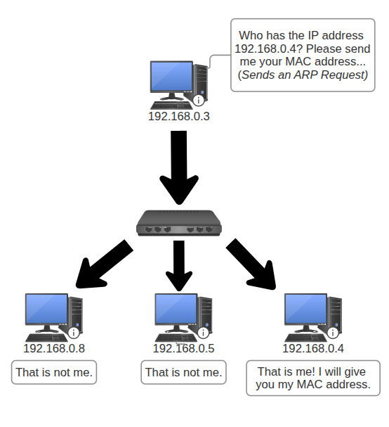
If such a case arises, here are the steps:
- It begins with the sender issuing an ARP request (broadcasting) to all devices in the local network
- Who has the IP address 192.168.0.4? Please send me your MAC address
- If the receiver determines whether it is the intended target, it will provide its own MAC address to the sender
- I am IP address 192.168.0.4. Here is my MAC address: 02:F3:A1:B7:6C:9D.
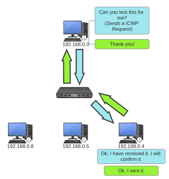
- The sender now knows the MAC address of the receiving NIC. It will now start sending a test packet to the receiver (ICMP OSI Layer 3) for diagnosis.
- Ok, thank you 192.168.0.4! Can you test this for confirmation?
- When the receiver confirms the test, they can now both interact with ease.
- Yes, this is good. Thanks 192.168.0.3.
| Steps 1-2 | Steps 3-4 |
|---|---|
 |  |
Thank you for reading! In the next chapter, we will dive into Layer 3 and 4.